WebGL tombstone - bump mapping
This post is part of a series on how to deform a 3D mesh (in this case, a tombstone) by drawing onto a 2D Canvas. To start from the beginning, click here.
In the previous post we looked at how to calculate the lighting for our tombstone in the fragment shader. While a vast improvement over a model with no lighting, the tombstone looked “faceted”, that is, it was apparent that it was made of a finite set of faces. In this post, we’ll look at how we can inspect the depth texture directly in the fragment shader and thus make our lighting model look even better.
To see the difference this makes, you can play around with the live demo. Use the ‘Toggle light’ button to switch between: no lighting, simple lighting, and the improved lighting covered in this post.
Here is a comparison of the two lighting schemes:
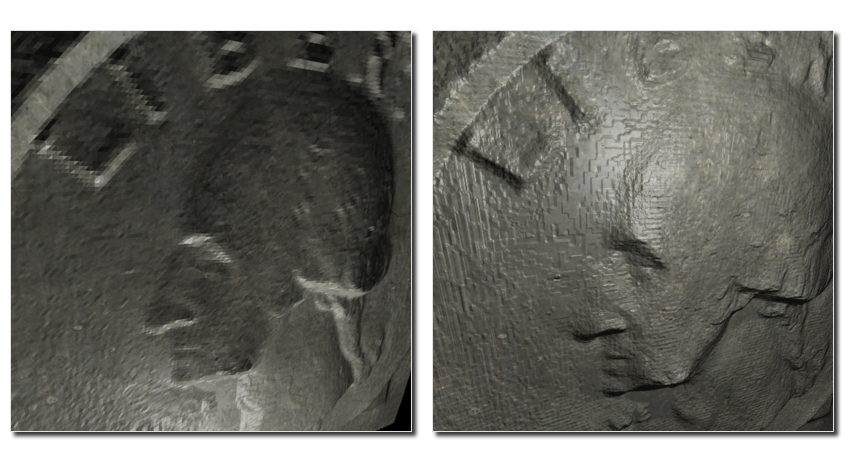
Notice in particular how the one on the left renders the details, like the letters, badly. While both models use the same shape for the mesh (and so have the same number of vertices), the image on the right inspects the depth texture when rendering the lighting, rather than basing the lighting on the position of the vertices.
Better shading
Recall that in the previous post, calculating the lighting was largely dependant on calculating the normal of the surface. To do this, we differentiated the surface, like so:
vec3 getNormal() {
  // Differentiate the position vector
  vec3 dPositiondx = dFdx(vPosition);
  vec3 dPositiondy = dFdy(vPosition);

  // The normal is the cross product of the differentials
  return normalize(cross(dPositiondx, dPositiondy));
}
The issue with this, is that our surface isn’t perfectly smooth, it is composed of faces defined by our mesh of vertices and as such the normal computed is the same across each face. This leads to the reflection of light being uniform across a face.
However, we can do better. We have the higher resolution depth map texture at our disposal, and we can use this calculate a more accurate value for our normal. The principle is similar to the code above, except that we correct the displacement vectors dPositiondx and dPositiondy by the value of the depth texture at that point:
vec3 getNormal() {
  // Differentiate the position vector
  vec3 dPositiondx = dFdx(vPosition);
  vec3 dPositiondy = dFdy(vPosition);
  float depth = texture2D(uCarveTexture, vUv).a;
  float dDepthdx = dFdx(depth);
  float dDepthdy = dFdy(depth);
  dPositiondx -= 10.0 * dDepthdx * vNormal;
  dPositiondy -= 10.0 * dDepthdy * vNormal;

  // The normal is the cross product of the differentials
  return normalize(cross(dPositiondx, dPositiondy));
}
Once we have the corrections to the depth, dDepthdx and dDepthdy, we modify the positions of the displacement vectors. You’ll notice that we use vNormal to do this, which is passed in from the vertex shader. Without the normal vector, a depth value wouldn’t be much use, as we wouldn’t know the direction in which the depth was to modify the position vectors.
I don’t know about you, but I find it pretty cool that this works. We’re essentially creating a variable, depth by doing a texture lookup and then telling GLSL to compute the derivative of this variable between fragments.
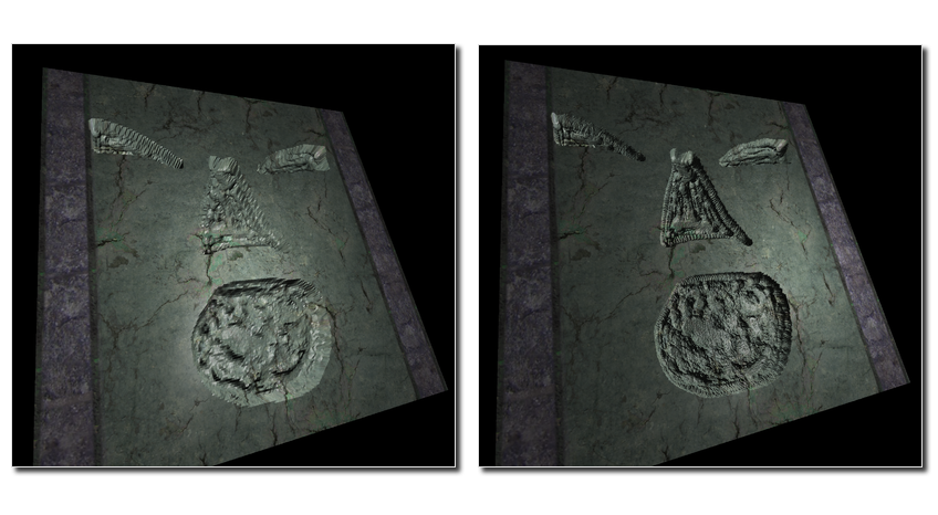
Here’s another example, again with the first image using the old technique. Notice how the reflections of the light are much higher resolution on the second image.
Bump mapping
What is interesting about the above approach is that we have made the light calculation independent on the position of the vertices. In fact, we can now use a much lower vertex count and still get a reasonable result. Here is the same model twice, except the version on the left has 40000 vertices on the side being carved, while that on the right has 4 (one at each corner).
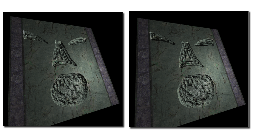
Notice that the lighting remains the same, the only difference is that the right model is lacking depth (most easy to see on the eyes of the model.
Using a texture in this manner is known as bump-mapping, and as the name suggests, is best suited to reasonably smooth surfaces, with small deformations, or bumps. At this level, there isn’t much point in having lots of vertices, as the perspective isn’t affected by these minor deformations. In the demo, you can toggle between a low vertex model and a high vertex model by using the ‘Toggle vertices’ button to see the difference.
For example, a bump map consisting of noise can give the surface the appearance of having lots of tiny holes.
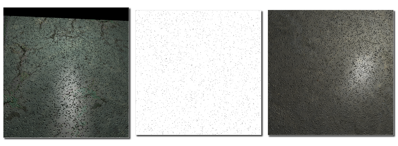
With such a depth map, it’s worth trying out the different lighting models. Because of the small feature size, the dents will only show up when using this post’s lighting model.